- General Information
- Project Team
- Architecture
- Structural
- Mechanical
- Electrical/Lighting
 |
Building Name: Doctors Community Hopsital Location: Lanham, MD (Near Washington, DC) Occupant Name: Doctors Community Hopsital Function: Hopsital Size: 270,000 SF expansion/renovation Stories: 5 Levels (All above grade) plus a mechanical penthouse Construction Dates: February 2007 to March 2009 Cost: Originally $34 Million, currently at $42 Million due to added scope (Total overall project cost) Delivery Method: Design-Bid-Build |
 |
Owner: Doctors Community Hospital, CM at Risk: Gilbane Building Company http://www.gilbanebuilding.com/ Architect: CR Goodman Associates http://www.crgoodmanassociates.com/ Mechanical and Electrical Engineer: Structural Engineer: Mincin-Patel-Milano http://www.mpm-engr.com/ |
ARCHITECTURE The vast majority of this expansion project revolves around the creation of more private patient rooms for the expanding hospital. Since patient care and comfort are at the forefront of the design, these rooms were all ringed around the perimeter of the building so that each room can have a window. Nurse stations, storage, elevator shafts, and other support type areas were put in the middle so as not to take away valuable patient room space that needs a view to the outside. The top 3 floors are arranged in this fashion. The second floor is currently just designated as shell space for future expansion. The ground floor is to be a new radiology suite and expanded emergency department. The exterior of the building is hand laid brick façade. In the majority of the new patient tower, the exterior is backed by metal studs 16” O.C. At stairwells, the exterior is backed by 10” CMUs. To help add visual interest to the façade, 8” split face CMU accent rows are placed on the North, East, and South elevations. They are located at an elevation just above each window lintel. Punch windows are the glazing of choice for this project, and all of them are non-operable. Cast stone sills at windows help to add another aesthetic splash to the façade.
The roofing system is built up on top of a steel deck that is either on top of the mechanical penthouse or 5th floor of the patient wing depending on where it is located in the footprint. The first layer placed down is 5/8” thick densglass waterproof gypsum board. This substrate is then topped with 3” of extruded polystyrene foam. A 1/4” overlay board suitable to accept the top coat is then placed. The final layer of this roof is a Styrene-Butadiene-Styrene modified bitumen roofing layer. This layer consists of a base layer, hot asphalt and a topping layer to create a waterproof system.
The major code that is governing the construction of this hospital is the 2003 edition of the International Building Code (IBC). NFPA 99, which is designed to help reduce risks of fire and explosions in healthcare facilities, also is guiding the design of this structure. Other codes that are being applied are various other NFPA guidelines, Maryland Elevator code (1990), International Energy Conservation Code (2003), International Mechanical Code (2003), WSSC Plumbing Code (2007), and various sections of COMAR (Code of Maryland Regulations). HISTORIC CONSIDERATIONS The building is not in a historic area of Prince George’s county, and the building itself is not historic, therefore no special historical requirements need to be met. ZONING My contact did not have the specific zoning requirements for Prince Georges County as they relate to this project at the time of our conversation, but he is looking into them and will have information back to me within the week. The information posted on Prince Georges County website gives insight to the zoning, however, there was no map or indication as to how this particular site was zoned. |
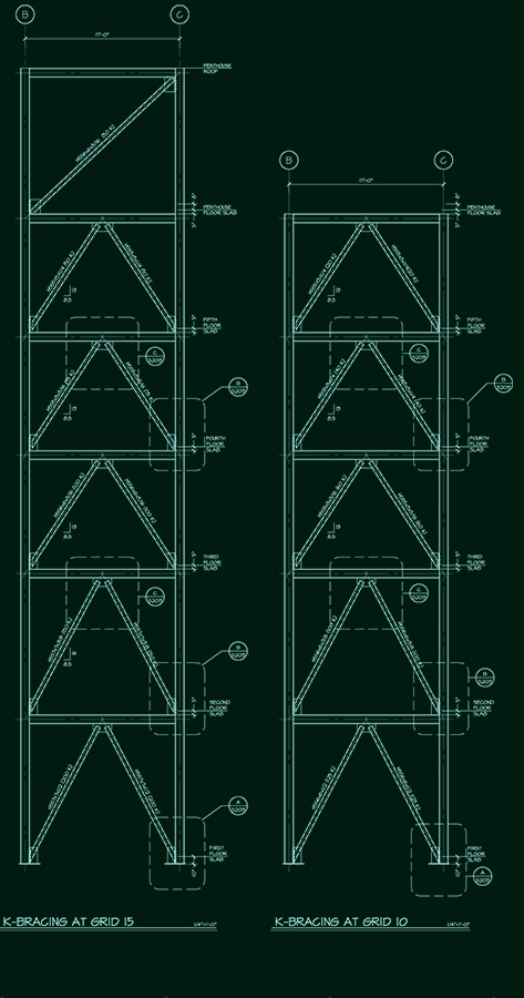 |
The main structure of this expansion is steel beams and columns with concrete on metal deck. Floor beams are typically W12x19 or W14x 22 varying between 6’ and 8’ on center. Columns are almost exclusively W12’s varying in lineal weights from 40 to 170 lbs depending on loads and locations. Some W8’s are used for columns with lineal weights varying between 30 and 70 lbs. The floor is typically 5” total slab thickness on metal deck (3 ½” topping slab on 1 ½” metal deck), comprised of 4000 psi lightweight concrete.
|
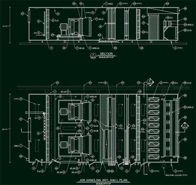 |
The mechanical system is quite a behemoth for this hospital. At the heart of the matter is 90,000 CFM air handling unit complete with twin 54” 125 HP fans doing half the load each. A 425 Ton chiller combined with a 425 ton draw through cooling tower takes care of the cooling load while three 2568 MBH boilers are utilized for the heating load. The air handler is fed with typical hot and cold water loops for the heating and cooling coils, and the entire system is located in a penthouse on the roof.
|
The electrical system in this building will be an extension of the systems currently already in place. Two existing 2500 Amp 480Y/277 switchboards have adequate ampacity but do not have space available for the new circuit breakers. As a result, many existing loads will be taken off the switch board and consolidated into two new distribution panels. This will free up enough space to allow the new wing to tie directly into the existing system. New 800 Amo breakers will be installed to feed the distribution panels for the new addition. N+1 redundancy for emergency power will be handled by a new 1000 KW generator to supply back up loads for the expasnion. The remainder of the hospital will stay tied into the existing generator plant which did not have sufficient capacity to accomodate the expansion. Electrical rooms are stacked on top of each other near the center of the building. Each room houses multiple distribution panels for each floor. |